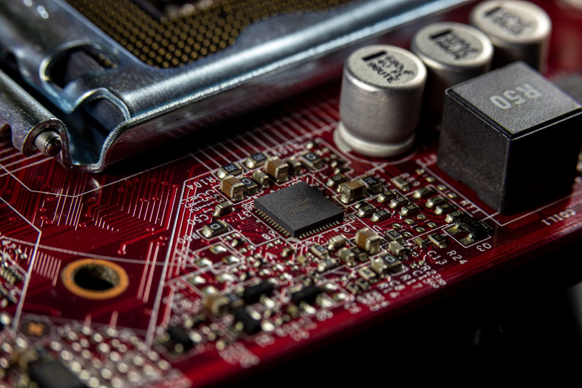
The Hidden Cost of Stock Nano Performance
For the hobbyist, the Arduino Nano is the quintessential workhorse. It is compact, breadboard-friendly, and surprisingly versatile. However, when your project transitions from blinking LEDs to precision measurement—such as reading a load cell, sampling an analog audio signal, or interfacing with sensitive RF transceivers—the stock design reveals its limitations. The primary culprit? Power supply noise.
Standard Arduino Nano boards are manufactured for mass-market cost-efficiency, not for signal purity. The decoupling capacitors included on these boards are often generic, high-tolerance ceramic types that exhibit significant Equivalent Series Resistance (ESR) and fluctuating capacitance under load. When you decide to upgrade Arduino Nano power decoupling capacitors for low noise, you aren't just changing parts; you are fundamentally altering the board’s ability to maintain a clean voltage rail, which is the backbone of any reliable precision system.
Understanding the Physics of Power Noise
To understand why decoupling matters, we must look at the "noise" in your circuit. Every time the ATmega328P processor switches its internal logic gates, it creates instantaneous current demands. These transient spikes cause minute voltage drops along the supply rails. If these drops are not dampened, they propagate through your board as high-frequency noise, which manifests as "jitter" in your analog-to-digital conversions or "ghost signals" in your digital communications.
By upgrading the decoupling capacitors, we create a local energy reservoir. This reservoir sits inches away from the silicon, providing the necessary current bursts before the main power source has a chance to respond. A "low noise" design minimizes the impedance path between this reservoir and the processor, effectively shunting high-frequency noise to ground before it can disrupt your sensor data.
Selecting the Right Components for Upgrades
Not all capacitors are created equal. When hardware modding for low-noise performance, you must move beyond generic components.
Ceramic vs. Tantalum vs. Polymer
- MLCCs (Multi-Layer Ceramic Capacitors): Excellent for high-frequency noise suppression due to their extremely low ESR. However, they can be piezoelectric, sometimes "singing" if the current demand fluctuates wildly.
- Tantalum Capacitors: The gold standard for stable capacitance over time and temperature. They have a very stable dielectric, though they are polarized and must be handled with care regarding voltage ratings.
- Conductive Polymer Aluminum Capacitors: These are the modern hero. They offer the extremely low ESR of ceramics with the high capacitance density of electrolytic caps. They are ideal for stabilizing the main 5V rail.
Recommended Upgrade Strategy
A robust decoupling strategy uses a "tiered" approach. You should aim to place a 0.1µF (100nF) X7R ceramic capacitor as close as possible to the VCC/AVCC pins of the ATmega328P to handle high-frequency transients, paired with a 10µF to 22µF low-ESR tantalum or polymer capacitor near the voltage regulator output to provide bulk energy storage.
Comparison: Stock vs. Optimized Decoupling
The following table illustrates the performance shift when moving from generic stock components to high-performance decoupling capacitors.
| Metric | Stock Nano Capacitor | Optimized Upgrade | Impact on Circuit |
|---|---|---|---|
| ESR (Typical) | 1.0Ω – 2.0Ω | < 0.05Ω | Reduced voltage ripple |
| Tolerance | ±20% | ±5% | Consistent stability |
| Temp Stability | Y5V (Poor) | X7R or Tantalum (Excellent) | Reliable in varying environments |
| High-Freq Filtering | Moderate | Superior | Cleaner ADC sampling |
| Bulk Energy | Minimal | High | Prevents brownouts during spikes |
Actionable Steps for Hardware Modding
Executing the upgrade requires steady hands and a basic understanding of SMD rework.
- Locate the Targets: Identify the decoupling capacitors near the voltage regulator and the VCC/AVCC pins of the ATmega328P chip.
- Removal: Use a fine-tip soldering iron with a bit of flux. Apply fresh solder to the existing joints to help transfer heat, then gently lift the component. Alternatively, use a hot air rework station set to 300°C.
- Cleaning: Use isopropyl alcohol (99%) and a cotton swab to clean the pads. Ensure no solder bridges exist.
- Soldering the Upgrade: Apply a small amount of fresh solder paste or tin to the pads. Position the high-performance capacitor and use the iron to tack one side before securing the other.
- Validation: Once complete, use an oscilloscope to probe the 5V rail. You should observe a significantly flatter DC line compared to the noisy, spiked signal seen before the modification.
The Role of PCB Layout in Noise Reduction
Hardware modding is not merely about the components; it is about the path they take. If you have the capability to design a custom PCB based on the Nano footprint, you must prioritize "star grounding." Ensure that the ground path for your decoupling capacitors connects directly to the analog ground plane if possible. Keep traces as wide and as short as possible. Even the best low-ESR capacitor will perform poorly if it is connected via a long, thin wire that acts as an inductor.
Final Thoughts on Signal Integrity
Upgrading Arduino Nano power decoupling capacitors for low noise is a "force multiplier" for any advanced project. While the stock board is sufficient for educational tasks, the real-world environment of industrial sensors, precision robotics, and high-fidelity signal processing demands more. By selecting high-quality tantalum or polymer caps and ensuring they are placed correctly, you transform your Nano from a generic prototyping tool into a robust, low-noise acquisition system.