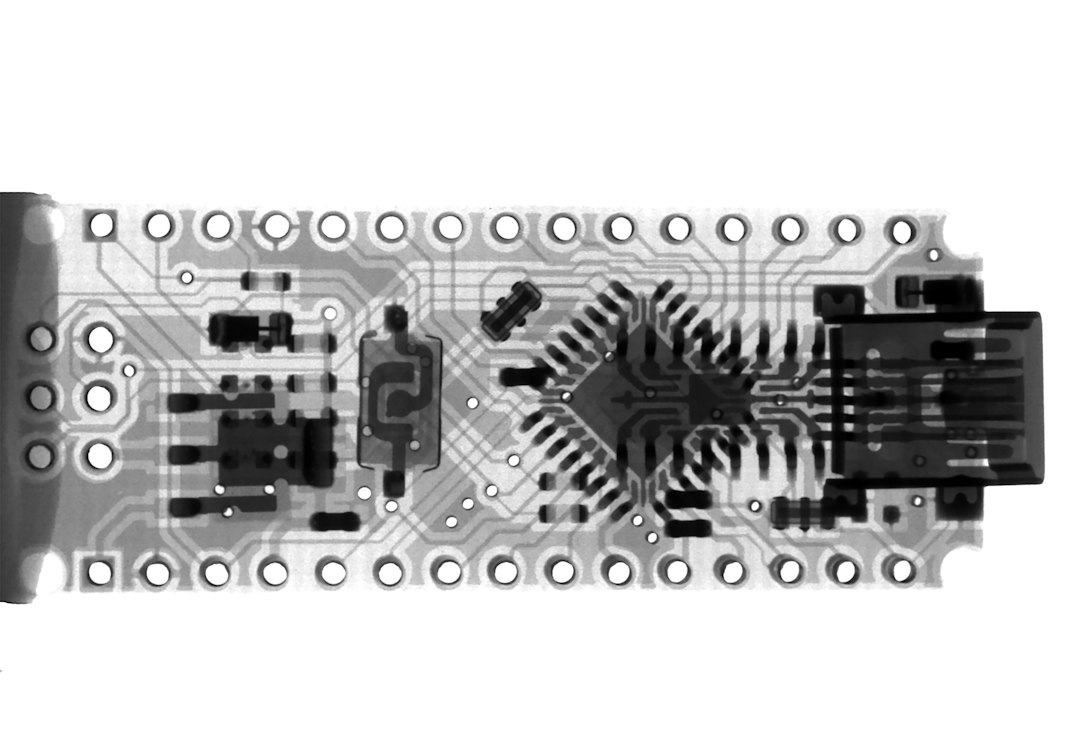
Why an External Voltage Reference Matters for the Arduino Nano ADC
The Arduino Nano’s analog‑to‑digital converter (ADC) is a 10‑bit, 0‑to‑5 V device. By default it uses the board’s 5 V supply as a reference, which can fluctuate with load or supply noise. Even a 1 % drift in the reference translates to a 5 mV error across the full scale, which is unacceptable for high‑precision sensing (thermocouples, MEMS, high‑resolution photodiodes, etc.).
Using an external precision voltage reference stabilizes the ADC’s reference voltage and decouples it from supply variations. This yields:
- Higher resolution: 10‑bit ADC → 1024 steps; a 4.096 V reference gives 4 mV per step vs. 5 mV with a 5 V reference.
- Better temperature stability: Many reference ICs have < 25 ppm/°C, far better than the Nano’s onboard regulator.
- Reduced noise: Dedicated reference ICs provide low output noise (µV‑level) and high impedance, protecting the ADC input.
Common External Reference Options
| IC | Nominal Voltage | Tolerance | Temperature Coefficient | Noise (rms) | Package | Typical Cost |
|---|---|---|---|---|---|---|
| REF5025 | 2.500 V | ±0.05 % | 10 ppm/°C | 4 µV | SOT‑23-5 | $0.70 |
| LM336 | 2.500 V | ±0.5 % | 100 ppm/°C | 10 µV | TO‑92 | $0.50 |
| TLV102 | 1.5 V | ±0.5 % | 100 ppm/°C | 5 µV | SOD‑523 | $0.30 |
| ADR4528 | 4.096 V | ±0.05 % | 10 ppm/°C | 2 µV | SOT‑23-5 | $1.20 |
| MCP1541 | 4.096 V | ±0.1 % | 20 ppm/°C | 3 µV | SOT‑23-5 | $0.90 |
Sources: manufacturer datasheets, 2024 revision.
Choosing the Right Voltage
- Linear ADC Scaling: The Nano’s ADC maps 0 V → 0, 5 V → 1023. If you use a reference of 4.096 V, the ADC range becomes 0–4.096 V, giving a 1.25 × improvement in resolution (4 mV steps).
- Sensor Output Range: Match the reference to the maximum expected sensor output. For a 0–3 V sensor, a 3.3 V reference gives a comfortable headroom.
Example: 4.096 V Reference with ADR4528
The ADR4528 is a 4.096 V reference with ±0.05 % tolerance and 10 ppm/°C temp‑coefficient. It’s ideal for many Nano projects because it matches the 1024‑step ADC perfectly.
Step‑by‑Step Build: Wiring an External Reference
- Select the Reference IC
Tip: For hobbyists, the ADR4528 or MCP1541 are cheap and stable. For ultra‑low‑noise labs, consider the REF5025.
- Power the Reference
- Connect the reference’s VDD to the 5 V rail.
- Ground the reference to the Arduino’s GND.
- If the reference requires a decoupling capacitor (typical 10 pF–100 pF), place it between VDD and GND as close as possible.
- Connect to the ADC Reference Pin
- On the Nano, the ADC reference pin is AREF.
- Pull‑up resistor: Add a 10 kΩ resistor from AREF to 5 V only if you’ll use the internal reference later. When using an external reference, tie AREF directly to the reference output.
- Configure the Arduino Code
```cpp
void setup() {
analogReference(EXTERNAL); // Tell the ADC to use AREF
}
void loop() {
int raw = analogRead(A0); // Read sensor
float voltage = raw * (4.096 / 1023.0); // Convert to volts
// Use voltage in calculations
}
```
Important: The analogReference(EXTERNAL) command must run before any analogRead().
- Calibration
- Measure the actual reference voltage with a calibrated DMM.
- Save the value in code or adjust the scaling factor accordingly.
Noise Reduction & PCB Design Tips
| Technique | Why It Helps | Implementation |
|---|---|---|
| Short, low‑impedance traces | Reduces inductive pickup | Keep AREF trace < 2 mm, use wide traces |
| Ground plane | Provides shielding | Use a 2‑layer PCB with a dedicated ground plane |
| Decoupling capacitors | Filters high‑frequency noise |