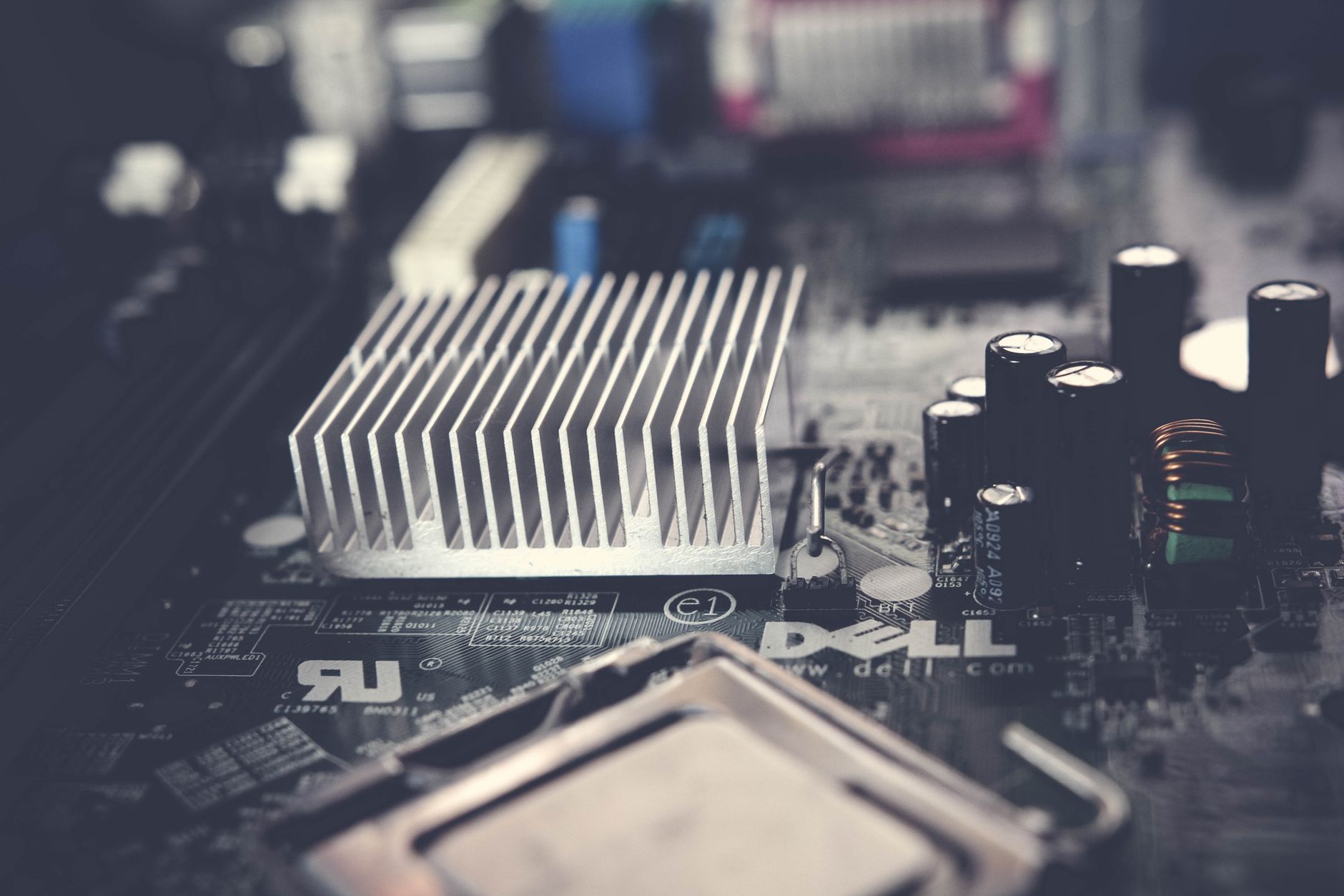
The Architecture of Precision: Why Custom Calibration Rigs Matter
In the realm of advanced electronics and industrial automation, the accuracy of your sensors is only as good as your calibration rig. Many engineers rely on "spaghetti" setups—tangled wires, breadboards, and unstable connections—which inevitably lead to signal degradation and inconsistent data. A custom shield board modular sensor calibration rig is the professional solution to this bottleneck. By moving away from loose prototyping and toward a dedicated, modular hardware interface, you ensure that every sensor unit tested under your roof meets the highest standards of accuracy.
Building a calibration rig is more than just soldering components; it is an exercise in signal integrity. A modular approach allows you to swap out sensors while keeping your core infrastructure—the power supply, the microcontroller logic, and the communication bus—stable and verified.
Designing Custom Shield Boards for Modular Sensor Calibration Rigs
The foundation of any robust calibration system is the shield board. Unlike generic development boards, a custom shield board allows you to integrate specific hardware requirements directly into the signal path. When designing for modularity, you must consider the "Common Interface" principle.
Key Design Considerations:
- Trace Impedance Control: Ensure that sensitive analog paths have proper clearance and shielding to avoid crosstalk.
- Galvanic Isolation: In industrial sensor testing, ground loops are the silent killers of precision. Incorporating isolation buffers on your shield ensures that the rig is protected and the noise floor remains low.
- Power Delivery: Modular systems often face voltage droop when multiple sensors are initialized simultaneously. Design your shield with dedicated local decoupling capacitors for every modular slot.
Hardware Modding and Upgrading Your Rig
Once you have established the base architecture, the next phase is hardware modding to optimize performance. Modular rigs are inherently upgradable, provided you build in sufficient "headroom" during the initial design phase.
When we talk about Hardware Modding in the context of calibration, we are often referring to the implementation of precision voltage references or the addition of high-resolution ADCs (Analog-to-Digital Converters). If your sensor outputs require a higher resolution than your primary microcontroller can provide, adding an external, high-bit-depth ADC directly onto the modular shield is a game-changer. This keeps the analog signal path short, minimizing the susceptibility to external electromagnetic interference (EMI).
Circuitry & Maintenance: Ensuring Longevity and Accuracy
A calibration rig is a long-term asset. If the rig itself drifts, your entire sensor ecosystem becomes unreliable. Maintenance of your custom shield board is not just about cleaning dust; it involves periodic verification of the calibration infrastructure.
The Maintenance Checklist:
- Connector Inspection: Modular pins are subject to wear. Use gold-plated, high-mating-cycle connectors to extend the life of your rig.
- Thermal Stability: Use an infrared thermometer to ensure that no components on your shield board are exceeding their rated thermal envelope, as heat-induced drift can skew calibration results.
- Reference Verification: If your rig uses a voltage reference chip, ensure it is periodically checked against a laboratory-grade multimeter (DMM).
Comparative Analysis: Breadboard vs. Custom Modular Rig
Choosing between a quick-and-dirty breadboard setup and a custom-engineered modular rig often comes down to the scale of your production. The table below highlights the performance disparity between these approaches.
| Feature | Breadboard/Jumper Wires | Custom Modular Shield Rig |
|---|---|---|
| Signal Integrity | Poor (High Noise/Inductance) | Excellent (Controlled Impedance) |
| Scalability | Low (Limited to one device) | High (Infinite modular slots) |
| Reproducibility | Low (High variance in connection) | High (Consistent contact pressure) |
| Durability | Low (Fragile, short lifespan) | High (Industrial-grade components) |
| Setup Time | Fast initially, slow in long-term | Initial investment, ultra-fast testing |
Firmware Integration and Automation
The hardware is only one half of the equation. To truly benefit from a modular calibration rig, your firmware must be designed to automatically detect which sensor module is plugged into the shield. This is best achieved using an ID resistor or an EEPROM chip on each module that reports the sensor’s unique calibration parameters and identity to the host controller via I2C or SPI.
By creating an intelligent "plug-and-play" handshake, you remove the risk of using the wrong calibration profile for a specific sensor, drastically increasing the throughput of your production line.
Future-Proofing Your Calibration Infrastructure
As sensor technology evolves—moving toward higher bit-depths, faster sample rates, and more complex digital protocols—your rig must be able to adapt. Avoid locking yourself into a single vendor's ecosystem. By designing your custom shield boards with standard headers and modular slots, you ensure that when the next generation of sensor chips arrives, you only need to swap the module, not the entire testing infrastructure. This "design-for-obsolescence" approach is the mark of a seasoned Senior Engineer.