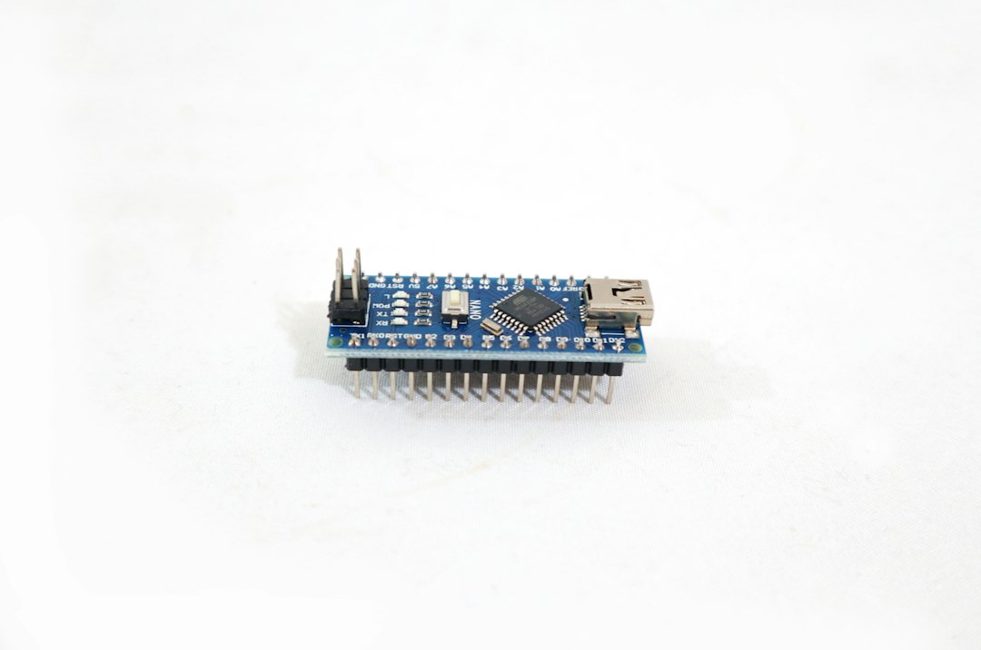
Understanding the Anatomy of the SPI Bus
The Serial Peripheral Interface (SPI) protocol is an ultra-fast, synchronous serial communication interface standard used by microcontrollers to communicate with one or more peripheral devices quickly. When working with resource-constrained microcontrollers like the Arduino Nano, the SPI bus is often the go-to choice for high-throughput components such as SD card modules, display screens (like the TFT LCD or OLED), and precision digital sensors (like the BME280, MPU9250, or MAX31855).
However, scaling up an embedded project to include multiple SPI-enabled components frequently triggers the dreaded arduino nano spi bus conflict multi sensor error. To understand why this happens, we must look at the bus topology. Unlike I2C, which uses device addresses, SPI relies on a master-slave architecture where the master (the Arduino Nano) controls the clock (SCK) and data output (MOSI) lines, while listening on the data input (MISO) line.
Every peripheral connected to this shared bus shares the exact same three lines (SCK, MOSI, MISO). To single out a specific device, the system uses a dedicated Chip Select (CS) or Slave Select (SS) pin for each sensor. When a CS pin is pulled LOW, that specific sensor wakes up and listens to or talks on the bus. When it is pulled HIGH, the sensor is supposed to disconnect its output buffers, placing its MISO pin into a high-impedance (High-Z) state.
Root Causes of Multi-Sensor SPI Conflicts on Arduino Nano
When you wire up multiple sensors to an Arduino Nano and start seeing garbage data, intermittent freezes, or completely unresponsive modules, you are experiencing bus contention. Pinpointing the root cause requires evaluating how the hardware and software interact.
1. Floating or Uncontrolled Chip Select Pins
If a sensor's CS pin is left floating or improperly tied to ground or VCC via code, the sensor never truly relinquishes control of the MISO line. When two sensors attempt to transmit data back to the Arduino Nano simultaneously, their output drivers fight each other. This electrical conflict can corrupt data packets, produce reading errors, and in worst-case scenarios, cause permanent thermal damage to the internal output stages of the sensor chips or the ATmega328P microcontroller.
2. Software Library Non-Coherence
Many third-party Arduino libraries for sensors are written in isolation. They assume they have exclusive access to the SPI bus. If Library A initializes the SPI bus with a specific data mode, clock speed, and bit order, and Library B re-initializes the bus with different parameters without restoring the previous state, unpredictable behavior ensues. Furthermore, if a library fails to explicitly handle the CS pin state before and after a transaction, other devices on the bus get accidentally activated.
3. Pin Limitation and Misconfiguration on Arduino Nano
The Arduino Nano provides a compact form factor with a limited number of digital and analog I/O pins. Developers often struggle to allocate enough digital pins for independent Chip Select lines, leading to improper sharing of CS lines (which completely breaks SPI functionality) or assigning pins that double as hardware interrupt pins or serial communication lines, causing overlapping hardware conflicts.
Comprehensive Diagnostic Workflow
Before rewriting code or tearing down your physical circuit, follow this structured diagnostic process to identify the exact source of your multi-sensor SPI conflict.
Step-by-Step Isolation Process
- Strip Down to a Single Sensor: Disconnect all SPI sensors from your Arduino Nano except for one. Upload a basic sketch to verify that the single sensor communicates reliably.
- Add Devices Incrementally: Reconnect the second sensor, making sure its Chip Select pin is wired to a completely distinct, verified digital pin on the Nano. Test communication again.
- Monitor MISO Behavior: Use a digital multimeter or an oscilloscope (if available) to inspect the MISO line. If the line remains locked HIGH or LOW when all CS pins are supposed to be HIGH, you have a physical hardware conflict or a tri-state output failure.
- Isolate Power Issues: SPI modules can draw significant instantaneous current. Ensure your Arduino Nano’s 3.3V or 5V regulator is not browning out when multiple sensors are active.
Step-by-Step Fixes for SPI Bus Conflicts
Resolving the arduino nano spi bus conflict multi sensor error requires a combination of robust hardware practices and disciplined software architecture.
Hardware Best Practices
- Dedicated CS Lines: Assign a completely unique digital pin on the Arduino Nano for every single peripheral's CS line. Never tie CS pins together unless utilizing specialized multiplexing hardware.
- External Pull-Up Resistors: Place a 10kΩ pull-up resistor on each Chip Select line. This ensures that during boot-up or microcontroller reset phases, all sensors remain safely in their deselected (High-Z) state rather than floating into an active state.
- Level Shifting: Ensure that if you are mixing 5V logic devices (like standard Arduino Nano models) with 3.3V sensors, you use proper bidirectional logic level converters on all SPI lines, especially MISO and SCK.
Software Implementation Strategies
To prevent bus contention in code, wrap every SPI transaction using the standard SPISettings transaction framework. This ensures that clock speed, bit order, and data mode are correctly applied right before talking to a device and safely released afterward.
| SPI Parameter | Standard Setting | Description / Best Practice |
|---|---|---|
| Clock Speed | 4 MHz - 8 MHz (Dependent on Sensor) | Match the slowest device on the bus to avoid timing violations. |
| Bit Order | MSBFIRST | Standard for almost all modern digital SPI sensors. |
| Data Mode | SPI_MODE0 to SPI_MODE3 | Check your sensor datasheets carefully; mixing modes without re-configuring causes corruption. |
| Transaction API | SPI.beginTransaction() | Always wrap communication blocks with transaction calls to maintain thread safety across libraries. |
Clean Code Example for Multi-Sensor SPI Handling
```cpp
#include
// Define unique Chip Select pins for two distinct sensors
const int SENSOR_1_CS = 10;
const int SENSOR_2_CS = 9;
// Define SPISettings with specific speed, bit order, and data mode
SPISettings sensorSettings(1000000, MSBFIRST, SPI_MODE0);
void setup() {
Serial.begin(9600);
// Initialize CS pins and set them HIGH (deselected)
pinMode(SENSOR_1_CS, OUTPUT);
digitalWrite(SENSOR_1_CS, HIGH);
pinMode(SENSOR_2_CS, OUTPUT);
digitalWrite(SENSOR_2_CS, HIGH);
// Initialize the SPI bus
SPI.begin();
}
void loop() {
// Read from Sensor 1
digitalWrite(SENSOR_1_CS, LOW);
SPI.beginTransaction(sensorSettings);
// Perform SPI read/write operations for Sensor 1
byte data1 = SPI.transfer(0x00);
SPI.endTransaction();
digitalWrite(SENSOR_1_CS, HIGH);
delay(50);
// Read from Sensor 2
digitalWrite(SENSOR_2_CS, LOW);
SPI.beginTransaction(sensorSettings);
// Perform SPI read/write operations for Sensor 2
byte data2 = SPI.transfer(0x00);
SPI.endTransaction();
digitalWrite(SENSOR_2_CS, HIGH);
delay(1000);
}
```
Advanced Optimization and Prevention Techniques
When scaling complex Arduino Nano projects, maintaining bus integrity is an ongoing requirement. Consider implementing these advanced practices to future-proof your multi-sensor array:
Avoiding Interrupt Collisions
The Arduino Nano relies on the ATmega328P, which has limited hardware interrupt capabilities. Ensure your SPI sensor interrupt lines (such as Data Ready DRDY pins) do not share vector footprints or conflict with critical system timings. Process sensor readings inside the main loop via polling or manage interrupts with extreme care.
Minimizing Trace Capacitance and Wire Lengths
SPI is designed for high-speed, board-level communication. Running long jumper wires (exceeding 15-20 cm) between your Arduino Nano and your sensors introduces parasitic capacitance on the clock and data lines. This leads to signal degradation, clock skew, and intermittent bit errors that mimic bus conflicts. Keep your physical wiring as short as possible and use shielded ribbon cables for complex layouts.