Understanding the Root Cause of PWM Frequency Interference
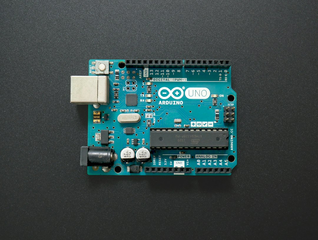
When prototyping automation systems, robotics, or environmental monitors using an Arduino microcontroller, engineers frequently encounter a frustrating issue: analog sensor readings fluctuate wildly the exact moment a DC motor, servo, or heater connected to a PWM pin activates. This phenomenon is known as pwm frequency interference analog sensor input arduino, and it represents one of the most common pitfalls in mixed-signal embedded systems design.
At its core, standard Arduino PWM pins (such as pins 3, 5, 6, 9, 10, and 11 on an Arduino Uno) do not output true analog voltages. Instead, they output a digital square wave switching rapidly between 0V and 5V. On the ATmega328P, this default switching frequency is approximately 490 Hz for most pins, while pins 5 and 6 run at roughly 980 Hz.
When these rapid square waves travel along adjacent traces on a perfboard, share a common ground wire, or draw current from the same regulated power bus, they generate high-frequency electromagnetic fields and voltage spikes (ground bounce). Because an Arduino's Analog-to-Digital Converter (ADC) measures voltage relative to its reference voltage ($V_{CC}$ or AREF), any high-frequency ripple on the power rails or signal lines directly corrupts the precision of the analog measurement.
Diagnostic Strategies: How to Identify PWM Noise
Before applying fixes, you must accurately diagnose the source of the error. Misidentifying noise can lead to hours of wasted code rewrites when the actual culprit is layout-based.
Step 1: Isolate the Hardware
Disconnect all high-power actuators (motors, MOSFETs, H-bridges) from the circuit while leaving the control logic connected. Observe the analog sensor readings in the Arduino Serial Monitor. If the sensor values stabilize immediately, you are dealing with conducted or radiated electrical noise rather than a faulty sensor.
Step 2: Use an Oscilloscope or Logic Analyzer
If available, probe the analog sensor input pin while the PWM signal is active. You will likely see high-frequency ringing or square-wave bleed synchronized perfectly with the PWM duty cycle.
Step 3: Check Common Impedance Coupling
Measure the voltage drop across your ground bus using a multimeter. If the ground rail fluctuates by more than a few millivolts when the PWM device switches, your star-grounding topology is inadequate, and switching currents are altering your system's reference frame.
Hardware-Level Fixes: Filtering and Isolation
Hardware solutions are always the most robust defense against electrical noise because they attack the interference at the physical layer before it reaches the microcontroller's ADC.
Building an RC Low-Pass Filter
The most effective way to clean a noisy analog sensor input is to construct an RC (Resistor-Capacitor) low-pass filter directly before the Arduino analog pin. This filter acts as a frequency-dependent voltage divider that allows low-frequency sensor changes to pass while shunting high-frequency PWM switching noise to ground.
- Resistor ($R$): Place a $10\text{k}\Omega$ resistor in series with the analog sensor output and the Arduino analog pin.
- Capacitor ($C$): Place a $0.1\mu\text{F}$ ceramic capacitor (or a $1\mu\text{F}$ electrolytic capacitor depending on response time needs) between the analog input pin and ground.
The cutoff frequency ($f_c$) of the filter is calculated using the formula:
$f_c = \frac{1}{2\pi R C}$
With a $10\text{k}\Omega$ resistor and a $0.1\mu\text{F}$ capacitor, the cutoff frequency is roughly $159\text{ Hz}$, which effectively strips out standard $490\text{ Hz}$ and $980\text{ Hz}$ PWM noise while leaving slow-moving environmental sensor data untouched.
Decoupling Power Supplies
Never power inductive loads like motors or solenoids from the Arduino's 5V output pin. Always use a dedicated external power supply for actuators, and tie all system grounds (Arduino ground, actuator power supply ground, sensor ground) together at a single, centralized point to prevent ground loops.
Software-Level Solutions and Timer Adjustments
When hardware modifications are limited, software techniques can mitigate the impact of PWM interference on analog readings.
Adjusting PWM Base Frequencies
By default, the Arduino core alters the Timer registers to generate audible PWM frequencies. You can change the prescaler on Timer 0, Timer 1, or Timer 2 to push the PWM frequency well above the audible and sampling range (e.g., up to $31\text{kHz}$), making it easier to filter out or shifting it entirely away from resonant frequencies.
```cpp
// Example for changing Timer 1 (Pins 9 and 10) to 31.25 kHz on an Arduino Uno
void setup() {
// Set prescaler for Timer 1 to 1 (Divisor = 1)
TCCR1B = _BV(CS10);
}
```
Synchronous Sampling
If your application allows it, avoid taking analog readings while the PWM pin is actively transitioning. By structuring your code to read the sensor during the "off" state of the PWM duty cycle or pausing PWM generation for a microsecond during analogRead(), you bypass the switching transient entirely.
Digital Filtering and Oversampling
Implement software moving-average filters or median filters in your Arduino sketch to smooth out erratic spikes.
```cpp
const int numReadings = 10;
int readings[numReadings];
int readIndex = 0;
int total = 0;
int average = 0;
void setup() {
Serial.begin(9600);
for (int i = 0; i < numReadings; i++) {
readings[i] = 0;
}
}
void loop() {
total = total - readings[readIndex];
readings[readIndex] = analogRead(A0);
total = total + readings[readIndex];
readIndex = (readIndex + 1) % numReadings;
average = total / numReadings;
Serial.println(average);
delay(10);
}
```
Comparative Analysis of Mitigation Techniques
| Mitigation Method | Implementation Complexity | Cost | Effectiveness Against PWM Noise | Impact on System Performance |
|---|---|---|---|---|
| RC Low-Pass Filter | Low | Very Low ($0.10) | High | Adds minor signal latency based on time constant |
| Star Grounding Layout | Medium | Free | Moderate to High | None (improves overall system stability) |
| Changing PWM Frequency | Medium | Free | Moderate | Can alter motor driver behavior or increase audible whine |
| Moving Average Filter | Low | Free | Low to Moderate | Introduces sensor response delay |
| Optoisolator / Isolation | High | Moderate ($2-$5) | Maximum | Requires isolated power domains |
Best Practices for PCB Layout and Wiring
If you are transitioning your Arduino project from a breadboard to a custom printed circuit board (PCB), proper layout practices will prevent pwm frequency interference analog sensor input arduino issues before they start.
- Keep Signal Traces Separated: Route analog sensor input traces as far away as possible from high-current PWM traces and power lines.
- Use Shielded Cables: For long sensor runs in noisy industrial environments, use shielded twisted-pair cables, grounding the shield at one end only.
- Use Ground Planes: A solid ground plane on a multi-layer PCB provides a low-impedance return path for high-frequency switching currents, drastically reducing electromagnetic emissions.