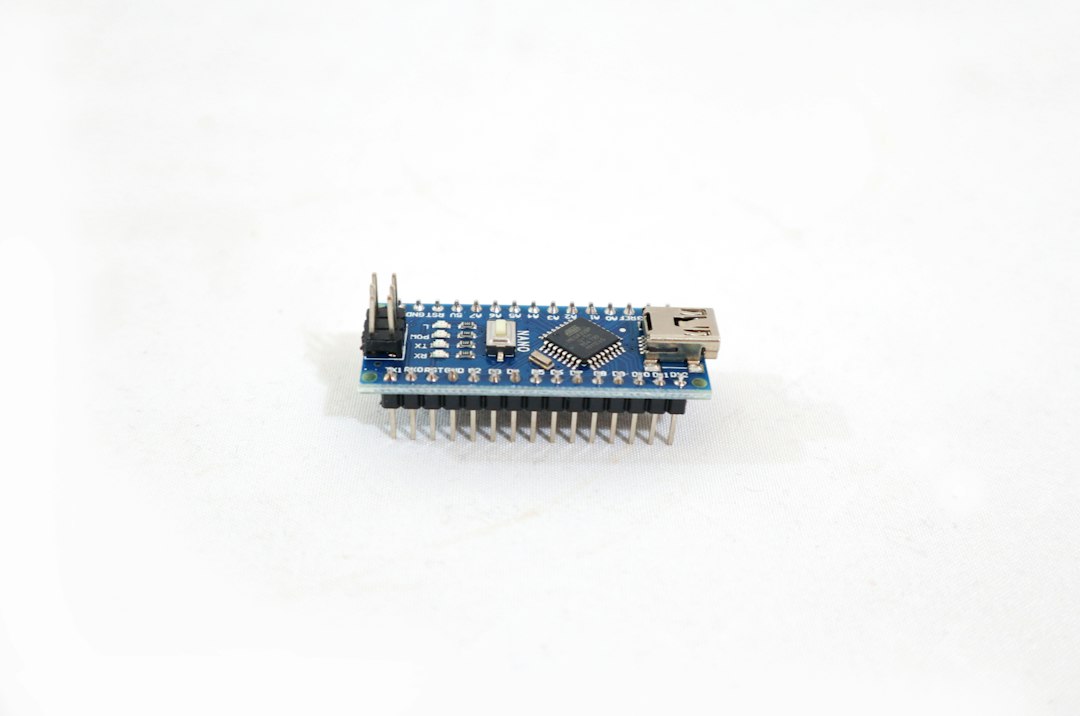
Understanding the Anatomy of an Overvoltage Failure on the Arduino Nano
The Arduino Nano has long been a staple in hobbyist and professional embedded systems development due to its compact footprint and robust feature set. Powered by the ATmega328P microcontroller running at 16MHz, the Nano features eight analog input pins (A0 through A7 on most layout variants). These pins are multiplexed into a 10-bit successive approximation Analog-to-Digital Converter (ADC). However, like all complementary metal-oxide-semiconductor (CMOS) integrated circuits, the ATmega328P is exceptionally sensitive to electrical stress.
When an overvoltage event occurs—such as accidentally connecting a 12V sensor output directly to pin A0, experiencing a severe electrostatic discharge (ESD), or encountering inductive kickback from a relay or motor—the internal protection diodes of the ATmega328P are forced into conduction. If the current flowing through these parasitic diodes exceeds their absolute maximum ratings (typically around 1mA to 40mA depending on the exact conditions specified in the Atmel/Microchip datasheet), the microscopic silicon pathways melt, fuse open, or short permanently to VCC or GND.
Recognizing the exact nature of this damage requires a systematic approach to diagnostic testing. Simply looking at the board is rarely enough, as silicon damage often occurs invisibly beneath the epoxy package or within the microscopic channels of the die itself.
Diagnostic Procedures: Confirming a Fried Analog Pin
Before diving into repair strategies, you must accurately diagnose whether the analog pin is genuinely fried or if you are simply battling a software configuration issue, a loose wire, or a bad sensor. Follow this step-by-step diagnostic workflow to isolate the fault.
Step 1: Visual and Thermal Inspection
Power down your Arduino Nano immediately and inspect the board under magnification. Look for discoloration, microscopic cracks in the ATmega328P chip package, or burnt traces near the analog header pins. Plug the board into USB while keeping all external peripherals disconnected. Carefully touch the surface of the microcontroller. If a specific internal section of the silicon is shorted out internally, the ATmega328P will often draw excessive current and become noticeably hot to the touch within seconds.
Step 2: Basic Continuity and Voltage Testing
Use a digital multimeter (DMM) set to diode test or resistance mode to check the pin in question.
- Measure the resistance between the damaged analog pin and GND.
- Measure the resistance between the damaged analog pin and the 5V rail.
- Compare these readings against a known-good analog pin on the same board.
If the multimeter shows zero ohms (a dead short) or an abnormal drop compared to healthy pins, the internal input stage of that specific ADC channel has suffered catastrophic silicon failure.
Step 3: Software Isolation Test
Sometimes, a misconfigured ADMUX register or improper analog reference (analogReference()) can make a pin appear unresponsive. Upload a clean, isolated diagnostic sketch that reads only the suspect pin and prints the raw integer value to the Serial Monitor.
```cpp
const int suspectPin = A0;
void setup() {
Serial.begin(9600);
pinMode(suspectPin, INPUT); // Ensure it's set as input
}
void loop() {
int sensorValue = analogRead(suspectPin);
Serial.print("Pin Reading: ");
Serial.println(sensorValue);
delay(500);
}
```
If the output is permanently stuck at 0 or 1023 regardless of whether the pin is floating, tied to 5V, or grounded, hardware destruction is confirmed.
| Diagnostic Method | Healthy Pin Reading | Damaged (Shorted to GND) | Damaged (Shorted to VCC) |
|---|---|---|---|
| Multimeter Resistance (to GND) | High / Infinite ($\text{M}\Omega$) | Near $0\,\Omega$ (Dead Short) | Moderate to High |
| Multimeter Resistance (to 5V) | High / Infinite ($\text{M}\Omega$) | Moderate to High | Near $0\,\Omega$ (Dead Short) |
| Raw Serial Output (Floating) | Fluctuating (Noise) | Locked at 0 | Locked at 1023 |
| Raw Serial Output (Tied to 5V) | 1023 | Locked at 0 | Locked at 1023 |
Repairing Burned Analog Pins: Feasibility and Realities
When working with surface-mount device (SMD) development boards like the classic Arduino Nano, users often ask: "Can I repair burned analog pins on an Arduino Nano due to overvoltage events?"
The short answer is nuanced. You cannot "heal" damaged silicon inside the ATmega328P microcontroller. Once an internal trace on the silicon die melts or welds shut, that specific hardware circuit is permanently dead. However, depending on your skill level, equipment availability, and project timeline, you have three distinct paths for handling the repair.
Approach 1: Chip-Level Rework (Replacing the ATmega328P)
If you possess a hot-air rework station, flux, solder wick, and steady hands, you can physically desolder the fried ATmega328P microcontroller from the Arduino Nano PCB and solder a brand-new blank ATmega328P in its place.
- Extraction: Apply flux generously around the pins of the ATmega328P. Use a hot-air gun set to approximately 380°C with low airflow to evenly heat all four sides of the QFP package until it lifts away cleanly.
- Cleanup: Clean the PCB pads using solder wick and isopropyl alcohol to remove old solder bridges and debris.
- Replacement: Align the new ATmega328P TQFP-32 package precisely with the PCB pads. Tack down two opposite corners with a fine-tip soldering iron, apply flux, and drag-solder the remaining pins.
- Bootloading: Since a replacement chip comes blank, you will need an external ISP programmer (like an Arduino as ISP or a dedicated USBasp) to burn the Arduino bootloader and upload your compiled firmware.
Note: Given the low retail cost of a replacement Arduino Nano clone or authentic board, chip-level rework is rarely economically viable unless you are doing it for educational practice or working under strict component-availability constraints.
Approach 2: Pin Redirection and Firmware Workarounds
If only one or two analog pins are burned out while the rest of the microcontroller functions normally, you can bypass the physical damage entirely through software remapping and hardware rewiring.
- Migrate to Unused Pins: If pin A0 is fried, move your sensor wire to A1, A2, A3, or higher (up to A7 on Nano boards). Update your code to read the new pin.
- Utilize Digital Pins as Digital Inputs/Outputs: If the analog multiplexer section associated with a specific pin is entirely destroyed, but the digital buffer of that pin remains intact, you may still be able to use it for basic digital reading or writing (
digitalRead()/analogWrite()), provided it hasn't formed a hard power short that drags down the whole port.
Approach 3: Complete Board Replacement and Root Cause Mitigation
For 95% of makers and engineers, the most practical solution to a burned analog pin is replacing the Arduino Nano entirely. However, simply swapping the board without addressing the root cause of the overvoltage will only result in a second fried microcontroller.
Preventing Future Overvoltage Disasters
Protecting your microcontroller from future transient voltage spikes, high-voltage sensor miswirings, and static discharges requires incorporating robust front-end protection circuitry.
1. External Clamping Diodes (Schottky Diodes)
While the ATmega328P has internal clamping diodes, they are exceedingly fragile. Adding external Schottky diodes (such as the BAT85 or 1N5817) from the analog input pin to GND and to the 5V rail safely shunts excess voltage away from the microcontroller.
```
5V Rail
[ ] Schottky Diode (Cathode to 5V, Anode to Pin)
Analog --+------------------> To Arduino Analog Pin
[ ] Schottky Diode (Cathode to Pin, Anode to GND)
GND
```
2. Current-Limiting Resistors
Place a series resistor (e.g., $1\,\text{k}\Omega$ to $10\,\text{k}\Omega$) between your analog signal source and the Arduino analog pin. According to Ohm's law ($I = V/R$), if an unexpected 12V signal hits the pin, a $10\,\text{k}\Omega$ resistor limits the fault current to a negligible level that the internal protection circuitry can safely handle without sustaining physical damage.
3. Voltage Dividers for High-Voltage Sensors
Never connect a sensor output that exceeds $V_{CC}$ (5V) directly to an Arduino analog pin. Always use a precision resistor divider network to scale down higher voltages (such as 0-12V or 0-24V industrial sensors) into a safe 0-5V range.
Conclusion
Dealing with burned analog pins on an Arduino Nano due to overvoltage events is a frustrating rite of passage for many electronics enthusiasts. While internal silicon damage cannot be reversed, understanding how to diagnose the failure, evaluating whether chip-level replacement is worth your time, and implementing rigorous front-end circuit protection will ensure your next prototyping session remains uninterrupted and robust.